TEL


TSS
Recommend
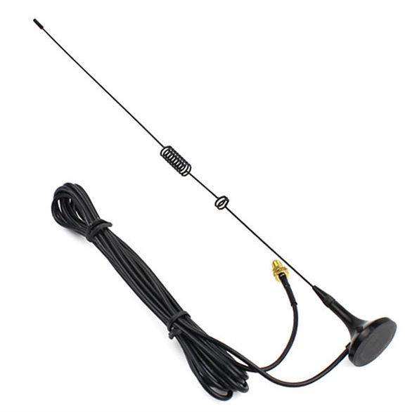
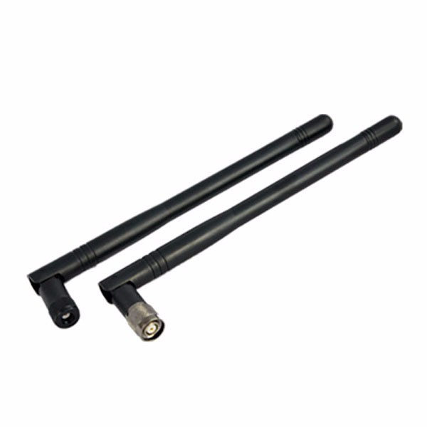
5dB Magnetic Sucker Antenna
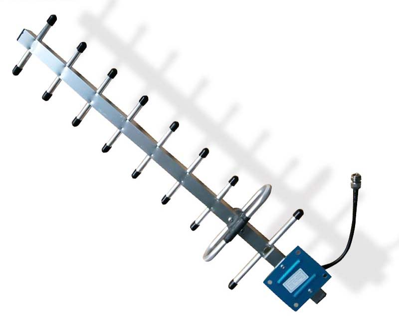
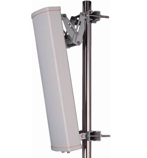
4G 9 Units Yagi Antenna
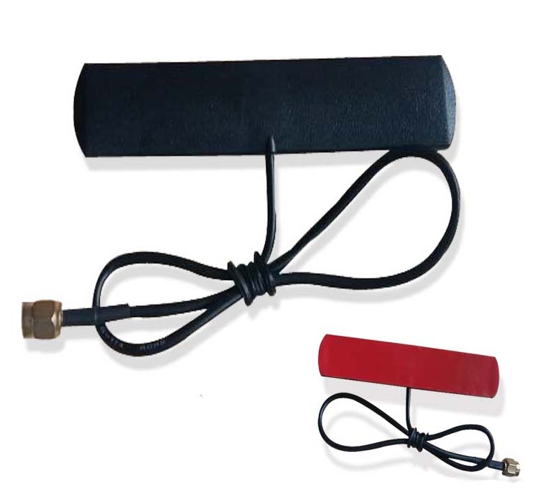
4G Patch Antenna
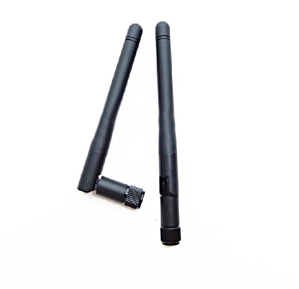
GSM Antenna
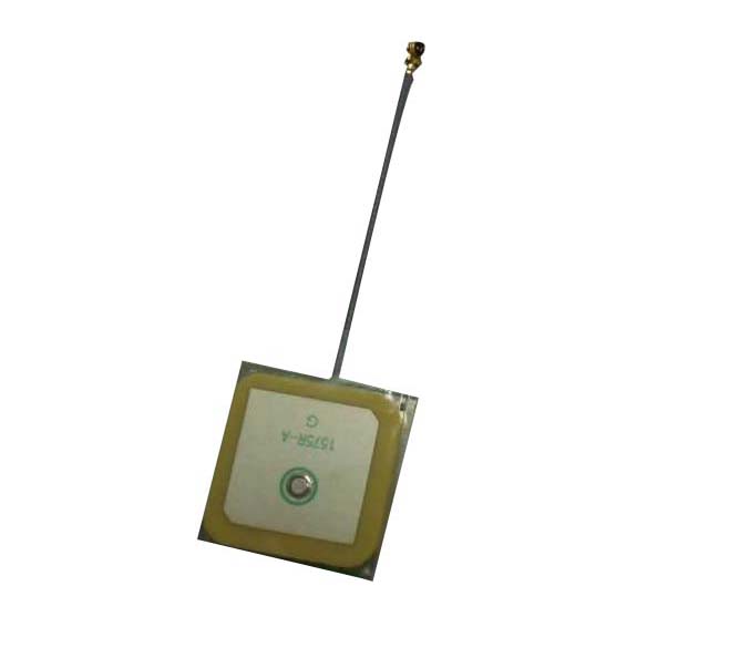
Internal GPS Antenna
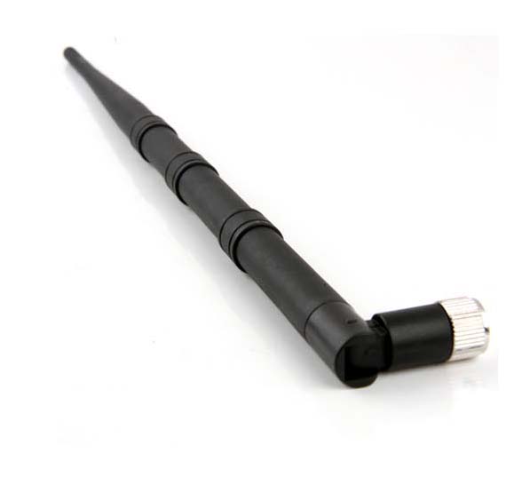
12dBi 2.4 GHz RP-SMA Wireless WLAN...
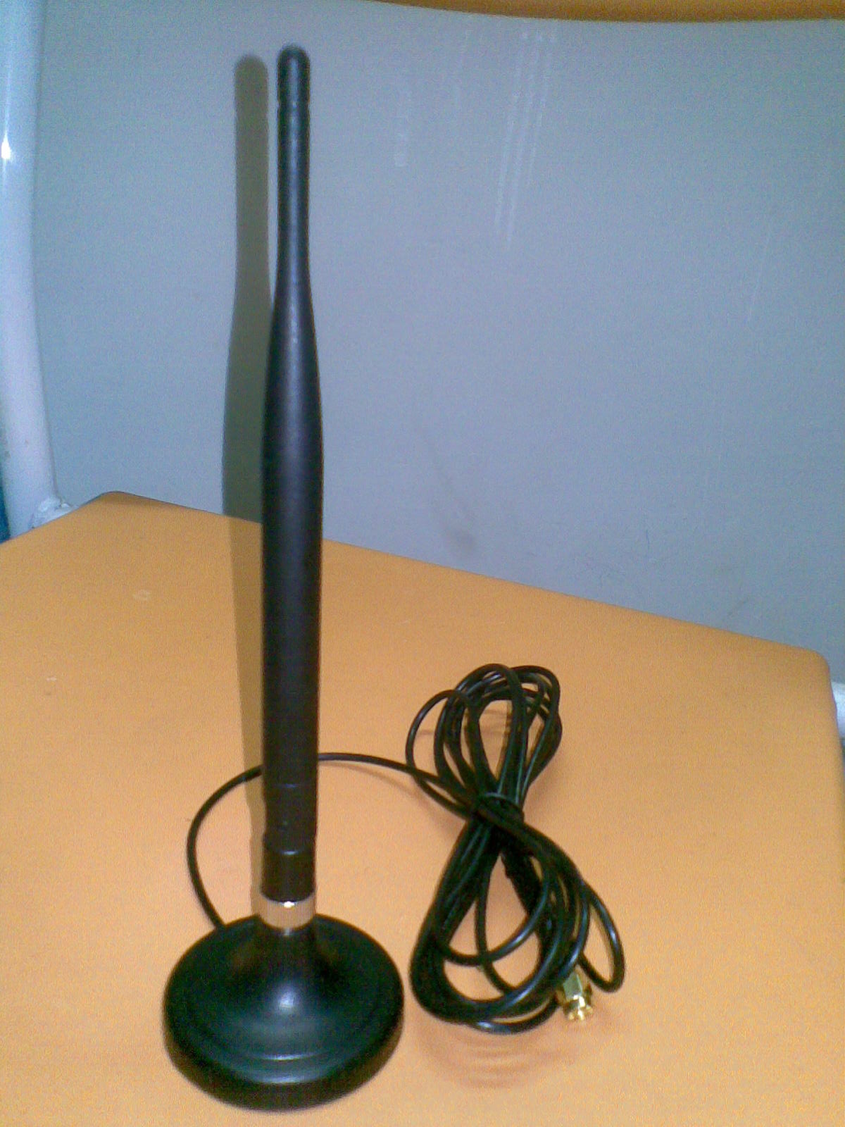
Magnetic Base Rubber Antenna
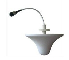
Indoor Omni Antenna
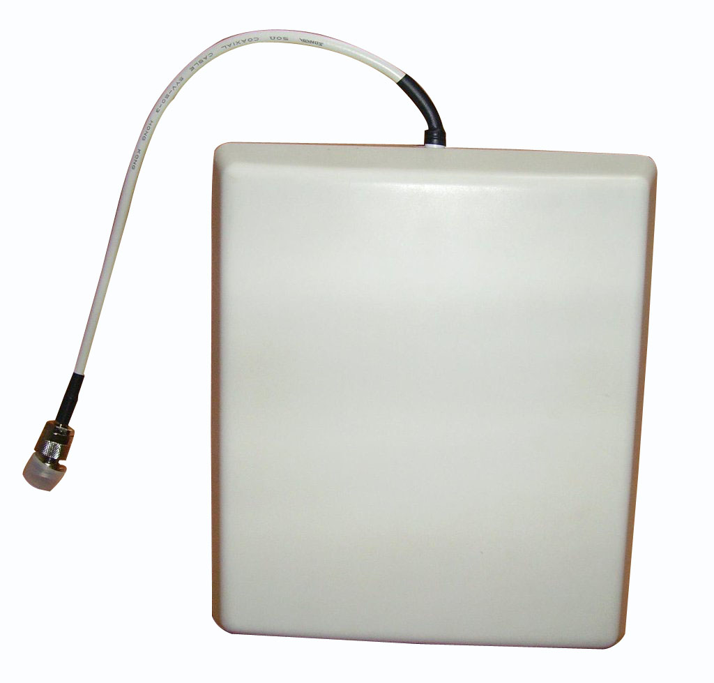
Outdoor Planel Wifi Antenna

Top Quality Wifi Antenna

High quality Antenna
Outdoor High Gain Embellished Platelike ...
High Gain 2.4G 12dBi WiFi Antenna
High Gain Wifi 6dBi 2.4GHz Antenna
High Gain 2.4G 9dBi WiFi Antenna
Contact
TEL+86-755-28608731
PersonMr. Wang
Phone+86-13631646215
E-mailfyx@fyx888.com
Technical Article HOME >> TSS >> Technical Article
First, the secret of the flat antenna structure If we cut the antenna surface of the flat antenna longitudinally, we will see that the antenna surface is composed of a five-layer structure. Figure one. The first and fifth layers are antenna protective layers, also called radomes, which are made of corrosion-resistant media. It plays the role of preventing oxidation, attenuating the influence of ultraviolet rays on printed circuit board, rain and snow erosion. These two layers are not shown in the structure diagram of FIG. The second layer is the receiving antenna layer. It is a printed circuit board metal layer, and there are many arrayed unit vibrator antenna arrays printed on it, so it can be called the antenna substrate layer. This layer determines the technical quality of the flat panel antenna. The unit dipole antenna can be diverse. The third layer is the dielectric layer of the printed circuit board, which supports the second layer. The fourth layer is a grounded conductor layer, which is a layer of metal foil that not only reflects the antenna array, but also can be another conductor of the feeder, forming a microstrip transmission line. The output of the antenna array is connected to the high frequency head installed behind the flat plate antenna plate. From this we can see that the flat panel antenna has a more complex structure and uses the microstrip circuit technology in microwave technology. The process required by it is very high, especially the phase homogeneity in the antenna array is extremely strict It is very different from the structure of the reflective parabolic antenna, so it is difficult to design and manufacture. The theory of flat panel antennas has been proposed for more than ten years. So far, no large number of high quality and low cost flat panel antennas have appeared in the domestic market. The reason is probably that.
2. The emergence of flat-panel antennas and their working principles. Live satellite television has increased the frequency to 12 GHz and shortened the wavelength to 2.5 cm, which has provided the possibility for the emergence of flat-panel antennas. In fact, the flat-panel antenna is transplanted from the array antenna commonly used in radar and communication to the Ku-band satellite TV receiving antenna. The so-called array antenna is formed by regularly arranging a lot of half-wave dipole unit antennas in rows and columns. Figure two. Generally, each adjacent half-wave oscillator unit includes a row pitch and a column pitch separated by an integer multiple of a half wavelength, thereby forming an antenna array. The number of half-wave oscillator units depends on the gain requirements of the flat-panel antenna. The higher the gain requirement, the more half-wave oscillator units it uses. For example, if the gain of a flat-panel antenna is required to reach 34dB, then there must be as many as 480 half-wave units of the flat-panel antenna. Therefore, the more vibrator units, the higher the gain, and the larger the area of the flat panel antenna. What is a half-wave dipole unit antenna?
(1) This is a pair of symmetrical antennas. The length of each end of the arm is 1/4 wavelength and the length of both ends is 1/2 wavelength. This type of antenna is called a half-wave dipole antenna. At this time, the half-wave oscillator is in a resonance state, the impedance is pure resistance and minimum, (75) has no reactance, and the loss is the smallest, so the radiation is the largest. Radiation pattern
(2), which uses the half-wave antenna as the axis, radiates to the surroundings perpendicular to the axis, and forms a figure-eight radiation from the cross section. If a reflector is added on the parallel side of the half-wave antenna,
As shown by (3), the radiation becomes unidirectional. In addition to the main lobe radiation, two side lobe radiations are added, ie, radiation in other directions is obtained, although smaller. When we understand the radiation characteristics of a single half-wave dipole antenna, we can analyze the antenna array formed by several half-wave dipole antenna units, that is, the characteristics of display antennas. Viewed from the direction perpendicular to the antenna array, since the incident radio waves have the same distance from each transducer, the phases of the radio waves are equal, and the radiation energy of the antenna array is the sum of the radiation of each half-wave oscillator, so the antenna array radiation is a multiple of a single oscillator. From the direction of the row and column planes of the antenna array, the travel distance of the incident wave to each half-wave oscillator is different, and the phase difference is half a wavelength. Therefore, the phase of each half-wave oscillator is half a wavelength apart, that is, 180 °. Therefore, the phases of the half-wave oscillators are only in phase, the radiations cancel each other, and the total radiation is zero. This means that there is no radiation in the planar direction of the antenna array. For other directions, as shown in Figure 4, the difference in the travel distance between the oscillators in this direction is L. It is not difficult to see that, because the radio waves in different directions, that is, the radio waves with different incident angles θ, the stroke difference L formed is not the same, and the radiation formed in this direction is also different, so there will be some different radiation, that is, side lobes. The number and intensity of sidelobe radiation is related to the number of half-wave oscillators. The more oscillators, the more sidelobes, the weaker. From this analysis, we know that the array antenna has the strongest radio wave energy in the direction perpendicular to the antenna surface, and the radio waves from the parallel direction of the antenna surface cannot be received. There is also a point of receiving radio waves in other directions, which is not welcomed by us. It can be eliminated by increasing the number of half-wave oscillators in the antenna array. Therefore, we can say that the main receiving direction of the flat panel antenna is perpendicular to the normal direction of the antenna.
3. Several equivalent radiating elements of a half-wave dipole unit in a flat-panel antenna In a flat-panel antenna, an array antenna is used, and its basic unit is a half-wave dipole unit antenna. And this basic unit, we can also call it the radiating unit of the antenna. In the Ku band, if the frequency range is 11.7u-12.75GHz, then the corresponding wavelength is between 2.353-2.564cm. The 1/2 wavelength is 1.177-1.282cm, which is the average value. In actual use, the half-wavelength is 1.23cm. Because the antenna has a shortening factor, the actual length of the half-wave oscillator unit must be multiplied by the shortening factor 0.85-0.9, so the actual half-wave oscillator unit length is 1.0455-1.107cm, and the average value is 1.076cm. Above, we analyzed that the basic unit or radiating unit in the flat panel antenna is a half-wave dipole antenna, but because it can only receive linearly polarized waves and has a single form, the size cannot be reduced. Therefore, in actual use, people often use other equivalent forms of radiating elements to replace it. The flat-panel antenna produced in this way not only has a smaller area and size, but some can receive circularly polarized waves. Let us now understand these equivalent radiating elements.
1. Sheet shape: as shown in Fig. 6, the pole piece composed of upper and lower electrodes is used as the radiation unit. There are many types of sheet-like graphics. Figure 7 shows an example of sheet-like shapes. Both of these examples are circularly polarized radiating elements.
2. Common surface electrode shape: As shown in 2 in Figure 6, it depends on the electrode and the surrounding ground wire. The coplanar electrode generates an electric field at its adjacent gap to radiate radio waves.
3. Bad seam shape: As shown in 3 in Figure 6, a closed waveguide is formed by two upper and lower metal plates, and the upper plate has a lot of bad seams, which guide the space radio waves and collect them inside to be guided by waves.
4. Linear shape: As shown in 4 in Figure 6, there is no unit oscillator, but the current distribution at different positions on the transmission line generates in-phase radiation. Therefore, the line is tortuous, the distorted part is a transmission line, and the straight part is a radiating element.
4. Feeding between radiating elements The feeding of radiating elements in a flat antenna is a difficult technical problem. It is necessary to ensure that the radiating elements are fed in-phase between them to make the flat antenna have a higher gain and a stronger Directionality. Each radiating unit relies on a microstrip feeder to feed power. The feed line must solve the problems of circuit impedance matching and phase connection. Because each radiating element vibrator is used in multiple connections, the impedance is continuously connected in parallel. The impedance is reduced by half every time it is connected in parallel, so the characteristic impedance of the feeder also needs to be changed to match it. The microstrip transmission line is made on the same substrate. It is impossible to change the impedance by changing the distance between the bands, so only the microstrip width can be changed to control the impedance change. In order to match between different line segments, there are also many λ / 4 impedance converters on the line. In order to ensure that the unit oscillators in different positions can be fed in the same phase, the microstrip lines between the unit oscillators are not the same length when wiring. In addition, in order to increase the antenna's ability to withstand rain and snow, the radio wave beam may not be perpendicular to the plane of the flat-panel antenna, but it is intentionally inclined upward by 15 ° -20 °. In this way, the antenna surface mounting pair can be vertical and nearly parallel to the wall surface. This is somewhat similar to the bias-feed antenna commonly used in the Ku-band. When installing, the antenna reflection surface must be inclined downward at an angle relative to the positive-feed antenna. When the flat-panel antenna is used to make the feeder, the length of the feeder between the two adjacent rows of vibrators is intentionally unequal, and the phase is shifted by an angle θ after current transmission. In this way, only when the radio wave is inclined to the flat plate, the current phases of the oscillators can be in phase, so that a signal is received. As shown in Figure 8. From this, we can see that by controlling the feeding phase between the elements of the flat plate antenna, that is, the radiating unit, to change the angle between the beam and the flat plate antenna, the electrical adjustment of the azimuth and elevation angles can be implemented. This is a major feature of the flat panel antenna, and it is also a major technical difficulty of the flat panel antenna, which is also unparalleled by the parabolic antenna. However, the angle of adjustment cannot be too large, otherwise the effective projection area of the antenna will be reduced, reducing efficiency and gain.
Fifth, the connection between the flat panel antenna and the high frequency head Because the radiating elements of the flat panel antenna are connected by the feeder, the radio wave has become an induced current at the vibrator. After the collective collection of each feeder line, it can be directly transmitted to the high frequency head in the frequency conversion Device. It does not need a feed source, and reduces the loss from the electric field form of the electric wave to the current form, which is beneficial to the reception of the signal. The high-frequency head at this time may be a concentrated parameter type or a distributed parameter microstrip type. Moreover, the high-frequency head can be installed directly behind the flat-panel antenna, or the micro-strip high-frequency head is directly built into the flat-panel antenna, so that the new structure of the antenna-high-frequency head integration is both beautiful and improved reliability. Do both.
6. The key technology of the flat panel antenna Because the flat panel antenna adopts the manufacturing process of the printed board, the productivity is more convenient than mechanical processing, the adjustment direction can be solved electrically, and the flat panel antenna can be integrated with the high frequency head. Is the advantage of the flat panel antenna. However, it is not easy to achieve the desired electrical performance of a flat panel antenna. The key lies in the loss problem. 1. Feeder transmission loss: In the flat-panel antenna, not only the half-wave dipole unit antenna works in the Ku-band, but the transmission feeders that feed the dipole-unit antennas also work in the Ku-band, with frequencies around 12 GHz. At such a high frequency, the loss of the feeder must be very large. 2. Feeder radiation effect: All feeders of the flat panel antenna have not only loss but also radiation. Due to the radiation of the feeder, the overall directivity pattern of the original design of the flat panel antenna was disturbed. 3. In the flat-panel antenna, the microstrip transmission line printed on the printed circuit board is a parallel double line consisting of two metal foils on both sides of the double-sided printed board. The electromagnetic field exists in the dielectric plate between the two metal foils. Since the medium works in the Ku-band, the losses are large. Even if a low-power dielectric printed board is used, losses still exist, so solving high-frequency dielectric losses is a major problem for flat panel antennas. At present, there are low-consumption dielectric products. 4. Matching loss. There are at least hundreds of radiating elements in each flat antenna. It is not easy to connect them all and match them. The more radiating elements, the harder it is to match. Mismatched connections are bound to increase losses. In addition, how to improve the efficiency of the flat panel antenna is another technical key to be solved. It involves the development of new dielectric materials, the design and development of new feeder structures, the development and practicality of Ku-band 12GHz microwave measurement technology and measuring instruments, and so on.
VII. How to select a flat panel antenna There is currently no technical standard for a flat panel antenna in China. It is difficult to say exactly how to select a flat panel antenna, especially an imported flat panel antenna. It doesn't just conform to a pair of imported flat antennas that can be used in China. Here we can only talk about how to choose a flat antenna in terms of practical aspects so that the selected antenna can be used.
1. Select the applicable frequency band of the flat panel antenna. Since the flat panel antenna is an antenna used for live satellite TV, and the flat panel antenna has a working frequency band, the flat panel antenna selected must be able to receive the frequency band that you plan to receive the satellite live broadcast. Although the working frequency band of the flat antenna has a full frequency band, such as 10.7 ~ 12.75GHz, it is not as good as the single frequency band such as 12.2 ~ 12.75GHz. Due to the obvious resonance characteristics of the flat panel antenna, if it exceeds the operating frequency band, it will detune and reduce the gain, and the effect is not good. Just like people buy clothes, although medium-sized clothes can be worn by both big and small people, the effect is not as good as tailoring.
2. Select the gain-frequency characteristic of the flat panel antenna. Through the working principle of the flat panel antenna, we know that the size of the radiating unit is determined by the operating frequency. So we naturally think that when the frequency or wavelength changes, can that fixed-size radiating unit still be a half-wave oscillator? If it is no longer a half-wave oscillator, it will no longer be in the resonance state, which will increase the loss and reduce the radiation, which means that the gain will become smaller. From this we feel that the wider the operating frequency range, the larger the non-resonant range, the larger the loss, the larger the gain reduction range, and the worse the gain-frequency characteristics. From this analysis, we should carefully understand at what operating frequency the gain data of a flat antenna is given. In other frequency ranges, will the gain still be this value? Therefore, we choose a flat plate antenna whose gain should be little or substantially unchanged throughout the entire operating frequency range. To be sure, the larger the operating frequency range, the more accurate the gain will remain unchanged.
3. Select the polarization of the flat panel antenna. On common parabolic antennas, there is no polarization problem, because it is a problem that should be paid attention to when selecting the feed source. However, on the flat panel antenna, there is a problem of what polarized wave is received.
4. Select the operating temperature range of the flat panel antenna. When the parabolic antenna is used, there is no operating temperature range at all, no matter the severe summer in the south or the severe cold in the north, it does not matter to the antenna. However, in the flat-panel antenna, its radiating unit and feeder use microstrip technology. The printed circuit board is composed of a thin metal plate. It has the problem of cold shrinkage and thermal expansion in the heat and cold. The size of the feeder changes, which affects the characteristics. Therefore, users in the north and south should consider this issue from the actual situation when selecting a flat antenna.
5. Select the noise temperature of the flat panel antenna. First of all, the lower the noise temperature of the flat panel antenna, the better. Broadly speaking, the noise of a flat panel antenna should be two parts, one is the flat panel antenna itself, and the other is the flat panel antenna. Introduced from outside.
6. Select the angle of incidence of the upward beam of the flat plate antenna to adjust the elevation angle. As shown in Figure 8, in order for the flat panel antenna to be hung on the wall and used to make an upward tilt angle, we hope that this angle can be adjusted to accommodate satellite incident waves at different orbital positions, and this angle. The adjustable range should be adapted to the adjustment range of the elevation angle of the flat panel antenna, so that the two adjustments are complementary. It is believed that with the development of science and technology, new and cheap flat-panel antennas will be developed and produced, which will greatly improve our satellite TV receiving technology and equipment.
Previous:What should I pay attention to...
Next page:How to install a car antenna?

A comprehensive enterprise specializing in the research, development, production and sales of electronic original device products. The company's independent research and development, independent production and independent sales, give customers the most transparent price!

Fei Yixun was established in 2006, and has more than 10 years of experience in the communications industry.It has provided communications solutions for large enterprises such as ZTE, Huawei, Foxconn, BYD, etc.

The company produces advanced testing equipment, network analyzers, spectrum analyzers, synthesizers, salt spray testers and other imported testing equipment, and is constantly pursuing better product quality.

Fei Yixun has rich industry experience. Customers can contact the company staff to make demands on their own. The company will explore according to the needs and develop the most reasonable solution for customers!

The company has a complete production and R & D system. The company focuses on the integration of new markets and the comprehensive combination of new product design and production technology, and is committed to developing new and innovative antenna products with high performance.

Comply with international standards, the products are sold to more than 30 cities across the country. The company provides complete product tracking services after sales. We can return or exchange you for quality problems!

Wechat QR code
LINKS

All rights reserved ©
FEIYIXUN Communication Equipment Co., Ltd. Filing: 粤ICP No.18101235
Address: Building F, No. 18, Ankang Road, Dakang, Tangkang, Henggang, Longgang District, Shenzhen, China
TEL:+86-755-28608731 email:fyx@fyx888.com Technical Support:XINQI
 English
 简体中文
简体中文 Popular searches: